
- July 8, 2025
- akil
- Piping Engineering
- No Comments
Unlocking the Future of Hybrid IT with Azure Hybrid Cloud and Azure Stack Edge
What’s in the blog
> What is a Stress Intensification Factor?
> Why SIFs Matter in Piping Stress Analysis?
In the field of piping design and stress analysis, ensuring the integrity and safety of piping systems under different loading circumstances is critical. One of the key concepts that plays a vital role in this process is the Stress Intensification Factor (SIF). SIFs are critical in predicting how fittings and components behave under cyclic loads, particularly those induced by thermal expansion or dynamic events.
What is a Stress Intensification Factor?
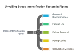
The Stress Intensification Factor (SIF) is a multiplier that is added to the nominal stress in a piping component to account for the additional stress caused by geometric discontinuities such as elbows, tees, reducers, and other fittings. Such discontinuities can have a major impact on fatigue life and failure potential by concentrating stress.
SIFs are defined in various piping codes, such as ASME B31.1 (for Power Piping) and ASME B31.3 (for Process Piping).In the recent transition the latest editions of ASME B31.1 and B31.3 strongly recommend the use of B31J for SIF calculations. ASME B31J provides standardized methods for calculating SIFs, particularly for non-standard or complex geometries, using approaches like finite element analysis.
 Why SIFs Matter in Piping Stress Analysis?
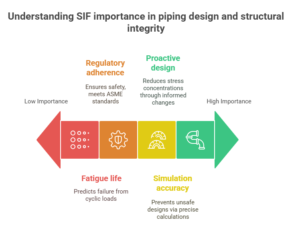
- Fatigue Assessment: Piping systems are often subject to thermal cycles and dynamic loads. These cycles can cause fatigue failure in areas with stress concentrations. SIFs help predict and mitigate these risks.
- Code Compliance: ASME piping codes require that piping stress calculations include the effect of SIFs to ensure a conservative and safe design, especially for components under displacement loads.
- Accurate Modeling: Software tools like CAESAR II or AutoPIPE use SIFs when performing flexibility and stress calculations. Incorrect or omitted SIFs can lead to inaccurate results and potentially unsafe designs.
- Design Optimization: Knowing where high SIFs occur allows engineers to make informed design changes—like replacing a branch connection with a weldolet or adjusting pipe routing—to reduce stress concentrations
 How SIFs Are Applied?
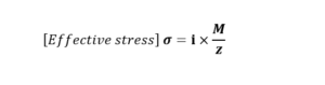
In analysis, the moment stress (especially for bending) at a piping component is multiplied by the SIF to yield the effective stress:
 Where:
= Stress Intensification Factor
M = Bending moment
z = Section modulus
This adjusted stress is then compared to allowable stress limits defined by the applicable code.
Common Misconceptions:
SIFs Are Not Safety Factors: They are not added margins, but rather adjustments to reflect the actual physical behavior of fittings under load.
Not All SIFs Are Equal: The values vary depending on geometry, orientation (in-plane vs. out-of-plane), and type of fitting. ASME codes provide tables and formulas for typical cases.
Real-World Example
Consider a system with a high-temperature pipeline containing multiple tees and elbows. Without incorporating SIFs, the analysis might show that the stress is within limits. However, when SIFs are applied, the stress at the tees might exceed the code allowable, indicating a fatigue risk. This insight could prompt the engineer to revise the design—perhaps by adding supports or changing the tee type—to improve durability and compliance.
InOpTra delivers end-to-end piping engineering services with cutting-edge technology and industry expertise. From design to implementation, we provide innovative, reliable solutions tailored to your project requirements. Trust our experienced team to optimize your infrastructure with precision and excellence. Contact InOpTra today for superior piping solutions.
